Making an IoT Garage Door Opener
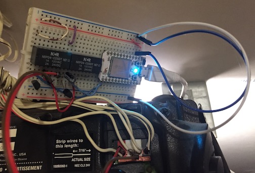
14 Nov 2017I live in a house with a garage and a few roommates. Because it’s California, nobody actually stores cars in the garage. We do keep stuff like bicycles and car covers there though! For a while, we had a wifi-based opener built by one of my roommates (based on a Particle Photon), but it was so IoT that it needed internet access and an in-home server for the web interface. Once the server in our house disappeared, we needed something new. This is what the old one looked like (until I disassembled it):
The most important feature the old garage door opener had was that by joining the local wifi, you could open and close the door. Since I was rebuilding it, I set a few other goals, such as making it work entirely on local wifi. This means if our internet goes down, we can still open the door!
There are three main parts to put together:
- Connect to the local wifi network
- Run a webserver that we can access
- Do some Electronics Things when we get certain web requests
The board I ended up using for the new one is the C.H.I.P., a $9 board that runs Linux, has onboard wifi and Bluetooth (solving part 1), and most importantly was in my roommate’s spare parts bin. Since it’s running Linux, that makes it easy to use modern web frameworks like Flask, neatly handling part 2. It also supports digital input and output pins (which gives a start on part 3).
The C.H.I.P. was already set up with their custom Debian install, so I connected to it via the serial port. After logging in, I used nmtui to connect to the wifi network used by our phones. The rest of the work was getting the application and associated hardware up and running. In the rest of this post, I’ll talk about my meandering path to getting something working, and close it out by presenting my final working schematic in addition to the webapp running the opener.
Toggling some outputs
The C.H.I.P. has a piece of hardware known as a GPIO (General Purpose Input/Output) expander. This is a very long way to say it can output 0s and 1s or read a digital signal from a pin. If you’ve ever used digital pins on an Arduino before, you’ve used a GPIO without even knowing it! Normally, GPIO devices have to be controlled in very low-level software, often by writing bits directly into memory. The next step was figuring out what I have to do on the C.H.I.P. to control its GPIO expander.
Linux makes our lives easier
Since I already had some vaguely-working circuitry from the previous opener, I left that alone and started by trying to get input / output working on the C.H.I.P. The documentation notes that there are eight GPIO ports provided by an I/O expander, and there are some fancy libraries for using it. I ignored this and promptly investigated the shell commands below. There was a lot of stuff about exporting the right port number based on your kernel version. I had no idea what this was talking about, and I decided to look further.
I discovered that sometime in the past several years, Linux grew a GPIO interface in SysFS! The documentation provides a clear explanation about how you can use this interface. From what I can tell, it’s designed for slower applications that aren’t timing-critical. In other words, it’ll work great for a garage door opener.
How do you use it?
The first step is figuring out which devices you have. If you look in /sys/class/gpio/, there are a bunch of entries like gpiochip408. These are the individual GPIO drivers available. The 408 is the first GPIO port on the device, and it maps to one of the pins on the GPIO output. Each device can have a bunch of pins, which means the 8th pin on gpiochip408 would be 415.
Running the shell command echo 408 > /sys/class/gpio/export will cause the kernel to make that GPIO available to you as a filesystem object! Note the fancy new /sys/class/gpio/gpio408 folder. This folder contains a bunch of files like value, direction, and active_low. You can read the value from value when the direction is in, or write 0 / 1 to it when the direction is out.
That’s pretty much it for things we will need to configure to make our GPIOs work. One of the interesting things about this abstraction is that it doesn’t get super technical and isn’t tied to the underlying electronics. This means that while you can’t express stuff like “this is an open-collector output, and you can enable or disable the pull-up”, it does make it extremely easy to work with, even from a shell!
How did I use it?
On the C.H.I.P. board I have, the GPIO expander starts at #408, which means it’s called /sys/class/gpio/gpiochip408 on the filesystem. Depending on your kernel version, this number might change! I started out by using just one pin. I figured out which pin mapped to which port by using the pinout in the documentation. For me, 408 maps to XIO-P0. The setup code in Python looked something like:
try:
    with open("/sys/class/gpio/export", "w") as f:
        f.write("408")
except:
    pass # The write fails if the pin is already exported
with open("/sys/class/gpio/gpio408/direction", "w") as f:
    f.write("out")
with open("/sys/class/gpio/gpio408/value", "w") as f:
    f.write("1") # The default value of the GPIO expander
In actuality, I tested this with the following shell commands, which turn the port on and off every second:
echo 408 > /sys/class/gpio/export
echo out > /sys/class/gpio/gpio408/direction
while true ; do
    echo 1 > /sys/class/gpio/gpio408/value
    sleep 1
    echo 0 > /sys/class/gpio/gpio408/value
    sleep 1
done
I then used my multimeter to measure the voltage between XIO-P0 and GND (ground). It worked! The pin toggled between 3.3V and 0V, which is the expected range for this chip.
Making sure the analog parts work
I hooked up the pin to an LED from my parts box in series with a 300 ohm or so resistor as a basic test:

The LED worked, but it was pretty dim. Some poking around on the internet led to me discovering that the GPIO expander hardware couldn’t produce a lot of current, which meant that this was expected behavior. I tried it with the existing board, but it didn’t really work. The current provided by the GPIO expander (the Texas Instruments PCF8574A) was so low it couldn’t even fully turn on the transistor that we used to switch power to the relays. According to the diagram on page 12 of the datasheet, the expander will only source 100 microamps! For context, a normal LED draws 20 milliamps, or 200 times more current.
Luckily, my roommate had a relay board with optoisolators on it. Optoisolators are normally used to electrically disconnect two circuits, such as when you have low-power electronics driving a high-power motor. It does this by having an internal LED turn on a phototransistor, in essence acting as a light-controlled switch! There is no electrical connection between the two sides. While the opener doesn’t need any electrical isolation, the low current required to enable a high-current output is useful to us. I hooked the optoisolator inputs up between the GPIO expander and 3.3V power, and it worked! It draws about 400 microamps, which is too much for the expander to source, but not too much for it to sink.

If you have questions about reading schematics, SparkFun has a good primer on it! In this schematic, pins 1 through 8 on the J2 correspond to XIO-P0 through XIO-P7.
If you’re wondering why there are two relays with a capacitor in series on one of them, it’s all due to how the actual garage door opener works. It measures the capacitance on the line and takes different actions based on the value read. Shorting the line opens / closes the door, and putting a 1µF capacitor in series toggles the light.
One interesting quirk of the GPIO expander is that all of the I/O pins are high by default (it says this on the first page!). One thing to think about is that we don’t want our garage door to toggle when we power on our board, so we want the default state to be safe. By providing power to one side of the optoisolator and hooking the negative side of the LED to the GPIO expander, there will be no current flowing through it by default. This means that the relay should be in the same position if the power is off completely or if the power has been turned on and the GPIO hasn’t been configured yet.
“Hardware isn’t hard”
Now that I’d worked out how to make a pin toggle its output whenever I wanted, I figured that the rest of the hardware would be easy and all I had left was the software (spoilers: I’d made some assumptions about the hardware that came back to bite me, but I’ll get to that later). I got a copy of the previous opener’s Python script from my roommate so I could make it less cranky and work with this new hardware.
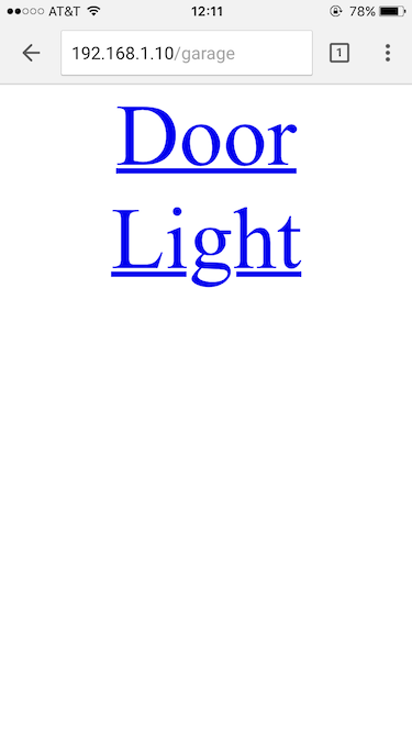
The opener program itself is a small webapp written in Python using the Flask framework. It exposes three endpoints: a page that displays two buttons (door and light), an endpoint that toggles the door, and an endpoint that toggles the light. It’s really basic, but it does the job.
One of the annoying parts of our old opener was that it didn’t “debounce” the “open door” link. Debouncing is the process by which we make sure what humans perceive as a single button press is interpreted by our program as a single button press. This was a problem when you pulled the page up on your phone, but it loaded slowly and you impatiently hit the “door” button again (which is of course not a thing that has ever happened to me). One of the easiest ways to implement debouncing is to have the program wait after it detects the first button click. By ignoring all additional button clicks in the next second or two, the number of false clicks goes way down! I implemented this with some basic synchronization primitives in Python:
class GpioToggler(object):
    def __init__(self):
        self.lock = threading.Lock()
        # Other initialization here

    def toggle_pin(self, pin):
        has_lock = self.lock.acquire(False)
        if has_lock:
            t = threading.Thread(target=self.worker,
                                 args=(pin,))
            t.start()
            return 200
        else:
            return 409

    def worker(self, pin):
        try:
            print "Toggling pin %s" % pin
            # Toggle the GPIOs here
            time.sleep(1.25)
            print "Unlocking!"
        except Exception as e:
            print "Something broke: %s" % e
        finally:
            self.lock.release()
I also abstracted out the hardware interface to make it easy to change the GPIO pin number in the future. While pins 408 and 409 work on this version of the C.H.I.P, that might not be the case on a Raspberry Pi or even a new Linux version on the C.H.I.P.! It’s not quite using a config file, but it’ll be really easy to abstract out when I want to.
class GpioToggler(object):
    def __init__(self):
        self.pins = {}
        self.set_up_pin("garage", "408")
        self.set_up_pin("light", "409")

    def set_up_pin(self, name, which, value="0"):
        self.pins[name] = which
	# All the GPIO sysfs operations happen here
        self.set_up_pin_raw(which, value)

    def toggle_pin(self, pin):
        if self.pins.has_key(pin) == False:
            print "Bad pin %s" % pin
            return 400
        # Do the pin toggling here
        return 200

@app.route('/garage/door')
def garage():
    toggler.toggle_pin("garage")
    return redirect('/garage')

@app.route('/garage/light')
def door():
    toggler.toggle_pin("light")
    return redirect('/garage')
The “last thing” left to do was plug in the relays and make sure everything functioned. I plugged it in, clicked on the “door” button, and it worked! I could hit the button, the relay would click on, and then click off. I was done! One last thing to check: does it open the door when I reboot the whole thing? This is a really important thing to consider, as the last thing you want your garage door opener to do is open the garage when you aren’t expecting it, such as after a power outage. It turned out that the door would in fact open when the device got rebooted, which meant I had to go back to the drawing board.
Hardware requires problem-solving
Why did the door open when I rebooted the C.H.I.P.? The symptom I saw was when turning the board on, the relays would click on for a moment and then turn off as soon as the on-board electronics had powered up, about a quarter of a second later. I wasn’t sure exactly what was causing this, but my guess wass that the GPIO expander wasn’t turning itself on as fast as it should. This meant that for a brief period of time, the expander would sink current from the optoisolator, allowing the relays to engage (and open the door accidentally). I was going to have to come up with a significantly more clever solution.
This whole project has been building stuff from my roommate’s junk bin, and I wasn’t about to stop now. The junk bin had a bunch of transistors (specifically the PN2222, which is an NPN-type transistor) which we’d used on the original board, so I set to work figuring out how to use a few of these in concert with the GPIO expander. My goal was to find some configuration that would not toggle the relays on startup while also working with the default-high output of the GPIO expander.
I eventually settled on a design that used one transistor per optoisolator as a switch. The positive side of the optoisolator LED was connected to 3.3V power, and the negative side was connected to the collector on a transistor. The base (which you can think of as the “switch input”) was hooked up to the GPIO expander. The trick was, instead of hooking up the emitter to ground, I connected it to the GPIO expander. What this means is that during startup, the base and emitter will be at the same potential the whole time. Transistors do all of their switching work based on there being a potential (i.e. non-zero voltage) between the base and emitter, so it stays completely off during startup!

To use this from software, I first have to set the two GPIO outputs to logic 0. Once I’ve done that, I can set the GPIO pin connected to the emitter to logic 0 as well, allowing it to sink current when the door or light transistors are switched back on. I can then toggle the two switch outputs at will, and it will operate the relay successfully! Note that if I did this in the opposite order and set the emitter GPIO to logic 0 first, I would accidentally turn on both relays. This is because the switch inputs were still high relative to ground, and when I set the emitter GPIO to logic 0, it creates a potential across the transistor, allowing it to switch on and let current flow through the LED.
This is the good-case timing diagram:
door          ______...---‾‾‾‾ ... ‾‾‾\____________________/‾‾\______
light         ______...---‾‾‾‾ ... ‾‾‾\____________/‾‾\______________
emitter       ______...---‾‾‾‾ ... ‾‾‾‾‾‾‾‾\_________________________

door relay    ________________ ... ________________________/‾‾\______
light relay   ________________ ... ________________/‾‾\______________
                    ^ power-on       ^             ^ light is clicked
                                     | program starts
And here’s what happens if we do it out of order, accidentally triggering both relays on program start:
door          ______...---‾‾‾‾ ... ‾‾‾‾‾‾‾‾‾\_______/‾‾\_____________
light         ______...---‾‾‾‾ ... ‾‾‾‾‾‾‾‾‾\________________________
emitter       ______...---‾‾‾‾ ... ‾‾‾‾‾\____________________________

door relay    ________________ ... _____/‾‾‾\_______/‾‾\_____________
light relay   ________________ ... _____/‾‾‾\________________________
                    ^ power-on          ^           ^ door is clicked
                                        | program starts
Putting it all together
The new hardware design required some additional code for the startup logic, but only a little bit! Once I verified that the script worked, I added a systemd unit file for the script to start it automatically on boot.
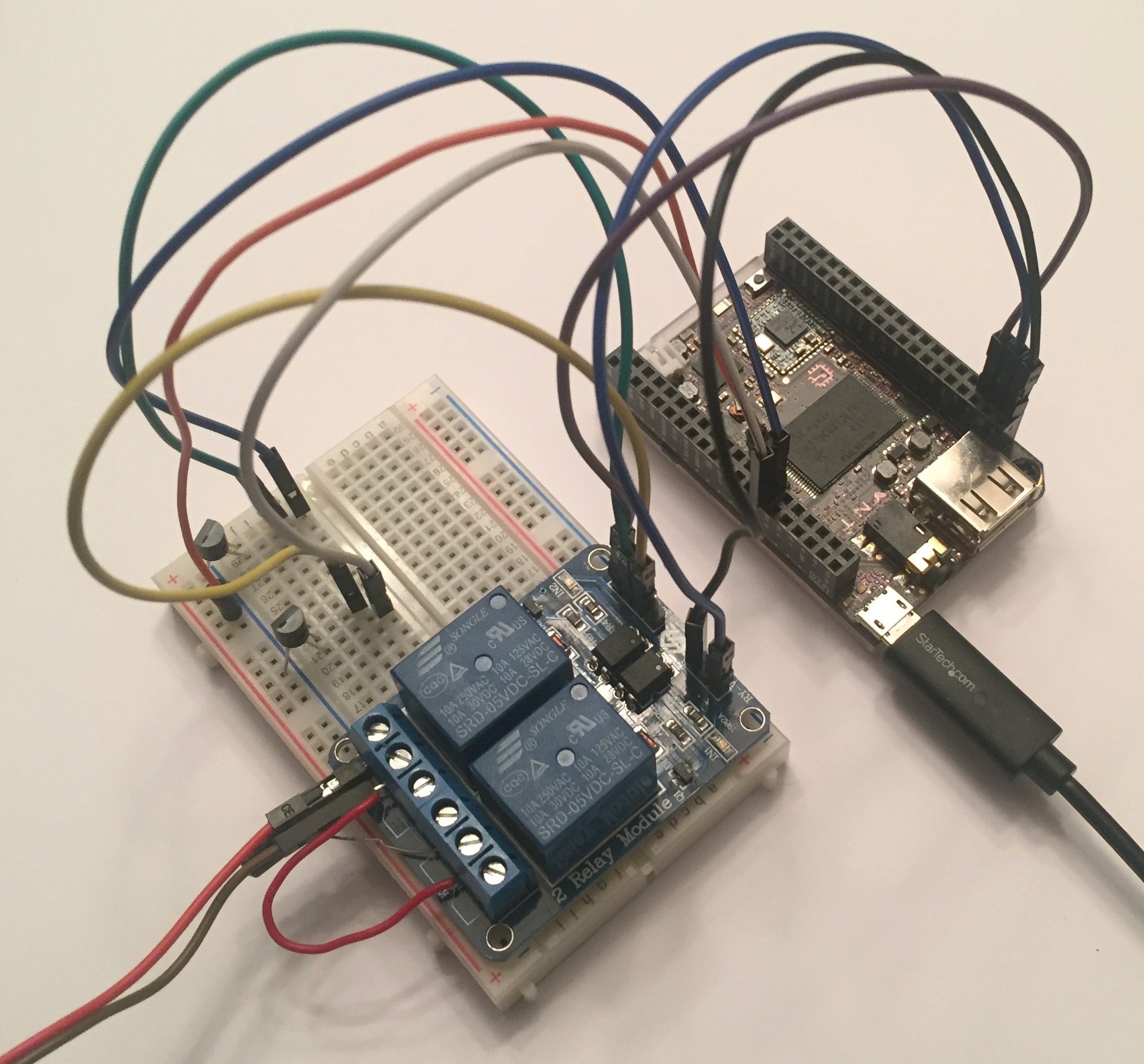
I used a small breadboard, the relay board, some double-sided tape, and a bunch of jumper wires to get the whole thing packaged up and ready to install. It now lives on top of my garage door opener, quietly waiting for one of us to click the button and have it do something useful. It seems a little silly to use an entire Linux system just to have a web page where I can click “open the door”, but this is the world we now live in. It’s definitely easier to glue together Python and GPIO files than to write low-level microcontroller code that serves a webpage. I put the code for the opener up on the internet so you can run your own wireless opener!
There are definitely future things I want to do with this! It would be nice to use the on-board Bluetooth chip to do BLE-based opening and provide iBeacon / Eddystone support. It would also be nice if I had an integrated app for my phone instead of having to pull up a web page. It could be fun to support user authentication and give time-based access to people or guests. It’d be helpful if it had audit logging. But these are all projects for another day!
Thanks to all who helped me review this before posting!